
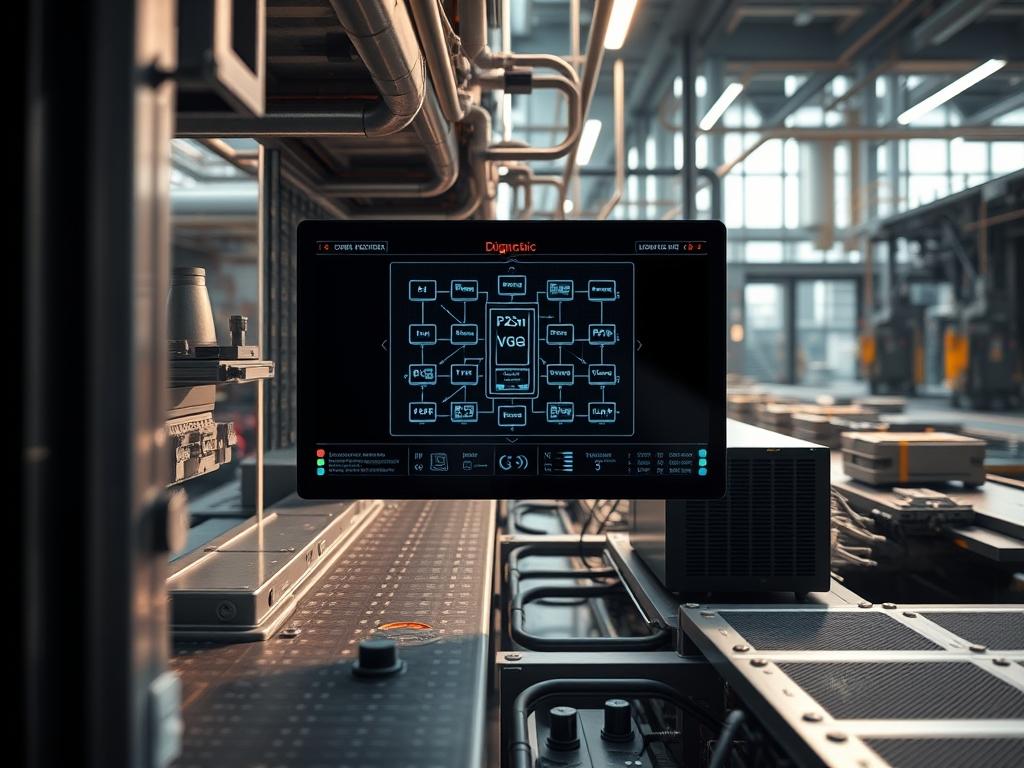
Effective grid stabilization relies on the sub-second coordination of Distributed Energy Resources (DERs). As the penetration of electric vehicles increases, the necessity for V2G Signal Response Time Testing becomes paramount for Transmission System Operators (TSOs). This manual details the rigorous auditing process required to verify that an Electric Vehicle Supply Equipment (EVSE) unit and the connected Electric Vehicle (EV) can respond to frequency regulation signals within mandated tolerances. The core problem addressed here is the latency introduced by the multi-layered communication stack: ranging from the high-level application layer protocols down to the physical Power Line Communication (PLC) modulation. Signal-attenuation and excessive packet-loss can delay the critical “Current Demand” instructions, potentially exacerbating grid oscillations rather than dampening them. By quantifying the delta between a “Secondary Control” dispatch and the physical change in current injection, architects can ensure the system provides a reliable, idempotent response. This manual provides the technical framework for such auditing, focusing on the ISO 15118 and IEEE 2030.5 interoperability standards.
Technical Specifications
| Requirement | Default Port/Operating Range | Protocol/Standard | Impact Level | Recommended Resources |
| :— | :— | :— | :— | :— |
| PLC Signaling | 2 MHz to 30 MHz | HomePlug Green PHY | 10 | IEEE 1901.1 Compliant Hardware |
| V2G Communication | Port 15118 (TCP) | ISO 15118-20 (EXI) | 9 | 1.2 GHz Quad-Core / 2GB RAM |
| Grid Dispatch | Port 443 / 608 | IEEE 2030.5 (SEP 2.0) | 8 | Hardware Security Module (HSM) |
| Measuring Latency | < 500ms (Total Delta) | NTP/PTP Synchronized | 9 | High-Speed Logic Analyzer |
| Thermal Limits | -25C to +50C | IEC 61851-1 | 7 | Passive or Active Cooling |
The Configuration Protocol
Environment Prerequisites:
Successful execution of V2G Signal Response Time Testing requires a controlled environment where the electrical and digital domains intersect. The auditor must ensure the following dependencies are met:
1. Installation of Linux Kernel 5.15+ with PREEMPT_RT patches to minimize internal processing jitter.
2. A functional CAN-utils suite for monitoring internal vehicle bus communication if vehicle-side logs are accessible.
3. Access to the EVSE Management System (EVSEMS) via a root shell or an authenticated OCPP 2.0.1 interface.
4. Synchronization of all testing equipment using a Precision Time Protocol (PTP) grandmaster clock to ensure sub-microsecond timestamp accuracy across the network.
5. Verification of OpenV2G or a proprietary ISO 15118 stack installation for message decoding.
Section A: Implementation Logic:
The engineering design of V2G Signal Response Time Testing hinges on the “Feedback Loop Latency” theory. We view the grid and the EV as a coupled dynamic system. The “Why” behind this specific setup is to isolate the sources of delay: the backhaul network latency (Cloud to EVSE), the local controller processing time (EVSE internal logic), and the physical power electronics transition time (Inverter switching). By employing Efficient XML Interchange (EXI) encapsulation, we minimize the payload size over the PLC link, yet the decoding process introduces overhead. Testing ensures this overhead does not exceed the thermal-inertia limits of the EV battery cells or the switching frequency constraints of the onboard charger. We utilize an idempotent testing sequence where the same power command is issued multiple times to calculate a statistically significant mean response time, filtering out outliers caused by transient signal-attenuation.
Step-By-Step Execution
1. Initialize High-Speed Network Capture
Deploy a network tap between the SECC (Supply Equipment Communication Controller) and the grid gateway. Execute the command: tcpdump -i eth0 -w v2g_capture.pcap port 15118.
System Note: This action captures the raw TCP streams at the kernel level. By bypassing standard application-layer logging, it eliminates the delay inherent in log-write operations, providing a “Ground Truth” timestamp for the incoming V2G payload.
2. Configure PLC Interface Attributes
Adjust the physical layer parameters to ensure an optimally clean signal for the HomePlug Green PHY link. Use plctool -i eth1 -w NMK to set the Network Management Key.
System Note: This ensures that the measurement environment is isolated from neighboring PLC networks. This prevents cross-talk and reduces the probability of packet-loss which could artificially inflate the V2G Signal Response Time Testing results.
3. Synchronize System Clocks via PTP
Execute ptp4l -i eth0 -m -s to synchronize the local EVSE controller clock with the grid simulator clock.
System Note: Precise time synchronization is critical. If the EVSE and the measuring device are out of sync by even 100ms, the response time audit becomes invalid. This command forces the local hardware clock to follow the PTP master, ensuring nanosecond-level alignment.
4. Inject Power Setpoint Dispatch
Through the Grid Simulator interface, send an IEEE 2030.5 DERControl message to the EVSE, requesting an immediate shift from 0kW to 7kW discharge.
System Note: This triggers the application-layer logic in the EVSE to begin the CurrentDemand renegotiation phase of the ISO 15118 protocol. It forces the system to move from a “Ready” state to an “Active Dispatch” state.
5. Monitor Control Pilot PWM Signal
Use a Fluke-190-Series oscilloscope to monitor the Pulse Width Modulation (PWM) signal on the Control Pilot pin. Match the change in duty cycle to the digital command received in Step 4.
System Note: This bridges the gap between the digital and physical layers. The change in the 1kHz PWM signal is the first physical reaction of the EVSE to the grid command. A delay here indicates high internal middleware latency or queuing issues within the EVSE OS.
6. Log the Inverter Current Step-Up
At the EV-side measurement point, capture the timestamp where the AC current crosses the 10% threshold of the target setpoint using a secondary high-speed sensor.
System Note: This is the final data point in the V2G Signal Response Time Testing sequence. The time difference between the initial packet arrival (Step 1) and this current ramp-up (Step 6) constitutes the total system latency.
Section B: Dependency Fault-Lines:
During the testing cycle, auditors frequently encounter “Time-Sync Drift.” This occurs when the PTP master and slave lose lock due to network jitter, leading to negative or impossible latency calculations. Another common bottleneck is “Execution Environment Contention.” If the EVSE is running secondary processes like GUI logging or intensive firewall auditing, the CPU throughput for EXI decoding drops, causing a spike in signal response time. Finally, ensure that the HomePlug Green PHY signal is not attenuated by high-frequency noise from nearby Variable Frequency Drives (VFDs), which can lead to frequent MAC-layer retransmissions and unpredictable latency.
THE TROUBLESHOOTING MATRIX
Section C: Logs & Debugging:
When a test fails the 500ms threshold, auditors must pivot to a granular log analysis.
1. Error Code: TIMEOUT_ISO_15118_SECC:
Check /var/log/v2g/evse-link.log. This usually indicates the SECC failed to acknowledge the PowerDeliveryRes message. Investigate the physical connection for signal-attenuation or inspect the iptables for rules blocking port 15118.
2. Error Code: JITTER_EXCEEDED_PTP:
Run pmc -u -b 0 ‘GET TIME_STATUS_NP’. If the master_offset exceeds 1000ns, the network switch likely does not support transparent clocking, introducing variable delay.
3. Physical Fault: PWM_SIGNAL_DRIFT:
Check the hardware logic-controller pins. If the PWM duty cycle is unstable (fluctuating more than +/- 0.5%), a ground loop is likely present between the EV and the EVSE, masking the signaling intent.
4. Log Path Analysis:
View dmesg | grep -i ‘eth’ to identify if the network driver is dropping packets at the NIC level. High rx_missed_errors suggest the CPU cannot handle the interrupt load during high-concurrency V2G sessions.
OPTIMIZATION & HARDENING
Performance Tuning:
To minimize latency during V2G Signal Response Time Testing, enable High-Performance mode on the controller CPU. Use cpupower frequency-set -g performance. Furthermore, adjust the sysctl parameters for the TCP stack: set net.ipv4.tcp_low_latency=1 and reduce the tcp_max_syn_backlog to prevent stale connections from consuming resources. These changes prioritize the processing of incoming grid signals over background maintenance tasks.
Security Hardening:
V2G systems are critical infrastructure. Ensure all IEEE 2030.5 traffic is encapsulated in TLS 1.2/1.3 using ECC-based cipher suites. Implement strict chmod 600 permissions on all private keys residing in /etc/v2g/certs/. At the physical layer, use a shielded cable for the Control Pilot to prevent signal injection or eavesdropping, which could be used to manipulate the response time measurements.
Scaling Logic:
As the number of EVs increases, the “Thundering Herd” problem arises. The V2G controller must handle high concurrency. Employ a “Leaky Bucket” algorithm for grid commands to ensure that the SECC does not crash when receiving thousands of simultaneous modulation requests. Use load-balancing at the grid gateway to distribute the EXI decoding load across multiple CPU cores, ensuring that response times remain consistent even under peak traffic.
THE ADMIN DESK
How do I reduce EXI decoding latency?
Switch to a pre-compiled schema approach using OpenV2G. Avoid dynamic schema negotiation during the handshake. Ensure the CPU governor is set to “Performance” to prevent frequency scaling delays during the XML-to-Binary conversion.
What causes periodic 1-second spikes in response times?
This is often caused by the Linux “Garbage Collector” or system logging (syslog) flushing to a slow SD card. Move /var/log to a RAM-disk or use a dedicated SSD with high IOPS to prevent I/O blocking.
Why does the EV ignore the PowerDeliveryReq?
The EV likely has a “Thermal Lock” on its battery. If the internal cell temperature is too high, the onboard battery management system (BMS) will ignore V2G discharge commands. Check the BMS status via the CAN-bus logs.
Is PLC signal-attenuation always a cable issue?
No. It can be caused by “Impedance Mismatch” at the coupling circuit of the EVSE. Ensure the coupling capacitor and transformer are matched to the 50-ohm characteristic impedance of the communication link to minimize reflections.
How do I verify the PTP sync status quickly?
Run the ptp4l utility with the -v flag. Look for the “rms” value; if it remains under 100, your synchronization is sufficient for sub-millisecond V2G Signal Response Time Testing.