
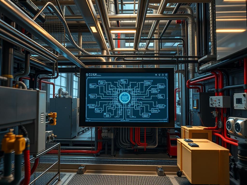
Microgrid Emergency Shutdown Logic (MESL) represents the critical fail-safe layer residing at the intersection of power electronics, industrial control systems, and high-availability software kernels. As modern microgrids integrate volatile distributed energy resources such as solar photovoltaics, battery energy storage systems, and reciprocating engines, the necessity for a deterministic shutdown sequence becomes paramount. This logic serves as the ultimate arbiter during thermal runaway events, frequency instabilities, or physical security breaches. Within the broader technical stack, MESL functions as an out-of-band management overlay; it must remain operational even when the primary control plane experiences high latency or packet-loss. The problem addressed by this implementation is the risk of cascading failures where a single component fault propagates through the microgrid, leading to equipment destruction or grid-wide instability. The solution is a tiered, idempotent shutdown protocol that decouples physical disconnects from software-state persistence, ensuring the system reaches a “Zero-Energy State” with minimal overhead and maximum reliability.
TECHNICAL SPECIFICATIONS (H3)
| Requirement | Default Port/Operating Range | Protocol/Standard | Impact Level (1-10) | Recommended Resources |
| :— | :— | :— | :— | :— |
| Logic Controller | 24V DC / 0.5A | IEC 61131-3 | 10 | 1.2GHz ARM / 2GB RAM |
| Network Interface | Port 502 (Modbus) | Modbus/TCP | 8 | Cat6a / Shielded |
| Physical Shunt | 120V – 480V AC | IEEE 1547 | 10 | Material Grade: 316 SS |
| Sensor Bus | 4-20mA Current Loop | ISA-5.1 | 7 | 18 AWG Twisted Pair |
| API Integration | Port 443 | TLS 1.3 / REST | 6 | 4-Core CPU (Cloud-Sync) |
| Relay Response | < 10ms | ANSI/IEEE C37.90 | 9 | Silver Alloy Contacts |
THE CONFIGURATION PROTOCOL (H3)
Environment Prerequisites:
Implementation requires adherence to NFPA 70 (National Electrical Code) and IEEE 2030.7 standards for microgrid controllers. Minimum software requirements include Linux Kernel 5.10+ for real-time patch support (PREEMPT_RT) or a dedicated PLC runtime environment like CODESYS V3.5. Users must possess sudo or root level permissions on the controller and Level 3 Admin access to the Human Machine Interface (HMI). Hardware dependencies include a Fluke-376 FC for amperage verification and a Logic-Controller with at least eight digital input/output (DIO) channels.
Section A: Implementation Logic:
The engineering design utilizes a “Normally Closed” wired logic philosophy to ensure that any loss of signal results in a safe-state transition. This design mitigates the risks associated with signal-attenuation over long cable runs. The software layer employs a “Watchdog Timer” mechanism; the software must pet the hardware watchdog at 100ms intervals. If the software hangs due to high concurrency or thread-locking, the hardware timer expires and triggers a physical shunt trip. This creates a fail-secure encapsulation where neither software bugs nor hardware malfunctions can leave the microgrid in an energized, uncontrollable state.
Step-By-Step Execution (H3)
1. Define Physical I/O and Memory Mapping
Assign the Digital Output (DO_01) to the Master Shunt Trip Relay. Open the PLC configuration utility and map the %Q0.0 register to this physical pin. System Note: This action bridges the software logic and the physical actuator: providing the base address for all subsequent commands.
2. Configure the ESD Watchdog Daemon
Navigate to /etc/systemd/system/ and create a file named esd_watchdog.service. Define the execution path to the binary located at /usr/local/bin/esd_monitor. System Note: By defining this as a systemd service: the kernel can automatically restart the monitoring process if it fails: reducing downtime and system overhead.
3. Initialize the Modbus TCP Polling Loop
Execute the command modbus_client –connect 192.168.1.50 –port 502 –write-register 0x800 1. System Note: This command initializes the communication link with the main inverter bank; it sets the initial heartbeat bit to “1” to signal the system is ready for operation.
4. Verify Physical Continuity with a Multimeter
Set the Fluke-multimeter to the continuity setting and probe the terminals between the Emergency Stop (E-Stop) button and the PLC Input (DI_01). System Note: This physical check ensures that signal-attenuation is not masking a wiring fault: which could prevent the shutdown signal from reaching its destination.
5. Set Permissions for the Shutdown Script
Run chmod 700 /opt/scripts/emergency_halt.sh followed by chown root:root /opt/scripts/emergency_halt.sh. System Note: Restricting file permissions prevents unauthorized users or compromised processes from intercepting or modifying the shutdown sequence: a vital security hardening step.
6. Test the Logic Gate Response
Manually depress the E-Stop and monitor the logic state using the command tail -f /var/log/microgrid/esd.log. System Note: This verifies the end-to-end latency of the system; the logs should show a timestamp transition from “System_Active” to “Hardware_Trip” in under 50ms.
Section B: Dependency Fault-Lines:
The primary bottleneck in MESL deployment is often “Signal Jitter” within the Modbus/TCP stack. If the network throughput is saturated by non-critical telemetry: the emergency payload may face significant latency. Another common failure point is “Thermal-inertia” in physical breakers; if a breaker has been cycled too frequently: its internal components may fail to trip due to heat expansion despite receiving the correct electrical signal. Always ensure that the physical hardware is rated for the specific load and ambient temperature of the site.
THE TROUBLESHOOTING MATRIX (H3)
Section C: Logs & Debugging:
When a fault occurs: examine the kernel ring buffer using dmesg | grep -i “esd”. Look for the error code 0xEF01: which indicates a “Watchdog Timeout.” If the hardware fails to trip: inspect the physical signal at the relay using a Fluke-multimeter to see if the voltage drops to 0V as expected.
| Error Code | Symptom | Path to Investigate | Probable Cause |
| :— | :— | :— | :— |
| ERR_MOD_TIMEOUT | Communication Loss | /var/log/modbus.log | Network packet-loss or high-latency. |
| 0x82_RELAY_FAIL | Mechanical Sticking | Physical Relay K1 | Thermal-inertia or contact welding. |
| SIG_ATTEN_LOW | Intermittent Signal | Shielded Cable Trunk | EMI interference or poor grounding. |
| AUTH_DENIED | Permission Error | /var/log/auth.log | Incorrect chmod/chown on shutdown script. |
OPTIMIZATION & HARDENING (H3)
– Performance Tuning: To minimize latency: isolate the MESL traffic on a dedicated VLAN. Use the chrt -f 99 command on the monitoring process to give it the highest possible real-time priority within the Linux scheduler. This ensures that even under high CPU load: the shutdown logic is executed without delay.
– Security Hardening: Implement a “Dead-Man’s Switch” in the logic. If the software controller does not receive an encrypted “Heartbeat” payload from the central auth server every 5 seconds: it should automatically initiate a controlled ramp-down. Close all unnecessary ports on the Logic-Controller using iptables -P INPUT DROP.
– Scaling Logic: As the microgrid expands: use “Distributed Logic Units” (DLUs). Instead of a single master controller: deploy localized PLC units for each generation asset. These DLUs should be interconnected via a redundant fiber-optic ring to prevent a single point of failure and to mitigate signal-attenuation across large geographical areas.
THE ADMIN DESK (H3)
How do I bypass a ghost trip caused by EMI?
Never bypass an ESD signal; instead: check the shielding on the Twisted Pair cables. Ensure the drain wire is grounded at only one end to prevent ground loops that introduce signal noise and false positives.
What is the “Idempotent State” in a shutdown?
It means that running the shutdown command multiple times results in the same safe state without errors. The script should check if the Shunt Trip is already engaged before attempting to re-send the payload to the relay.
Why is my PLC showing 40% packet-loss?
This typically points to a duplex mismatch on the Ethernet port or a failing RS-485 transceiver. Check the termination resistor (normally 120 ohms) at the end of the physical bus to ensure signal integrity.
How do I handle thermal-inertia in high-load breakers?
Incorporate a cooling-off timer in the software logic. Prevent the system from “re-closing” a breaker for at least 300 seconds after a trip to allow hardware components to dissipate latent heat and return to nominal tolerances.